Residential moisture management suffers from a fundamental metrics problem. Consumers and standard review aggregates consistently evaluate dehumidifiers using a single, flawed variable: the manufacturer-stated pint capacity. This metric, typically measured under ideal laboratory conditions of 65% relative humidity and 80°F, fails to predict real-world performance. In practice, a dehumidifier operates within a dynamic microclimate governed by thermal fluctuations, air exchange rates, and structural vapor barriers. Selecting an environmental control system based on raw capacity without calculating the specific latent heat load leads to cyclic short-cycling, accelerated compressor failure, and systemic energy waste.
Optimizing indoor air quality requires a structural understanding of psychrometrics—the study of thermodynamic properties of moist air. To stabilize an environment, a dehumidifier must remove moisture at a rate that equals or exceeds the continuous vapor influx from both internal generation (cooking, respiration) and external infiltration. In other news, read about: The Apache Wingman Delusion Why Drones Won’t Save the Attack Helicopter.
The Thermodynamic Constraints of Moisture Extraction
Dehumidification is not a simple filtering process; it is an energy-intensive phase change. To evaluate any machine, we must first analyze the two dominant mechanical architectures: compressor-based (refrigerant) systems and desiccant-based systems. Each operates under entirely different thermodynamic constraints.
Compressor Systems and the Dew Point Bottleneck
Refrigerant dehumidifiers utilize a fan to draw moist air over an evaporator coil cooled by a chemical refrigerant loop. As the air temperature drops below its dew point, water vapor condenses on the coil surface and drains away. The cold, dry air then passes over a condenser coil, where it recovers the heat rejected during the cooling cycle before being exhausted back into the room. MIT Technology Review has provided coverage on this critical issue in great detail.
The core limitation of this mechanism is its dependency on ambient thermal energy. When the room temperature drops below 65°F, the dew point falls correspondingly. The evaporator coil must become significantly colder to induce condensation. This induces localized freezing, covering the coils in frost.
When frost accumulates, the machine must enter a defrost cycle, shutting down the compressor and running only the fan to melt the ice. During a defrost cycle, the net moisture removal rate drops to zero while energy consumption continues. Consequently, in subterranean environments like basements, a high-capacity compressor model can see its real-world extraction efficiency decline by up to 60%.
Desiccant Systems and the Thermal Penalty
Desiccant dehumidifiers bypass the dew point bottleneck entirely. Instead of cooling the air, they pass it through a rotating wheel impregnated with a moisture-absorbing chemical, typically silica gel. A secondary, heated air stream (the regeneration loop) continuously bakes the collected moisture out of the wheel, exhausting it into a collection tank or external drain.
Because desiccant models do not rely on condensation via cooling, their extraction rate remains completely linear from 100°F down to 33°F. However, this independence introduces a significant operational trade-off: high energy consumption. Heating the regeneration loop requires substantial electrical wattage. A desiccant unit extracting 20 pints of water per day will often consume more kilowatt-hours than a 50-pint compressor model operating in its optimal thermal zone.
Quantifying the Indoor Vapor Load
Before deploying hardware, the total latent load of the structural envelope must be calculated. Relying on simple room square footage ignores the volume of the space and the structural infiltration rate. The true load is a function of three core variables.
- Infiltration Matrix (Air Changes per Hour - ACH): Every time outdoor air enters a structure, it carries a specific grain weight of moisture. A poorly sealed basement with a high ACH will introduce a continuous moisture load that can overwhelm a standard residential unit.
- Internal Generation Vector: Human metabolism, showering, and appliance usage add predictable masses of water to the air. A single occupant contributes roughly 0.1 pounds of water vapor per hour through respiration and transpiration alone.
- Capillary Inversion: In below-grade spaces, hydrostatic pressure forces liquid water through porous concrete foundation walls. This moisture evaporates immediately upon reaching the interior surface, creating a invisible, continuous vapor drive.
To simplify these variables into a functional procurement framework, environments can be classified into four distinct operational bands:
Damp (Relative Humidity 60%–70%)
Space feels musty only in humid seasons. Floor surfaces remain dry to the touch. The moisture load is primarily driven by standard atmospheric infiltration.
Very Damp (Relative Humidity 70%–80%)
Space always smells musty. Minor damp spots are visible on concrete walls or floors. Moisture is actively migrating through the boundaries.
Wet (Relative Humidity 80%–90%)
Moisture actively beads on walls or floors. Seepage is present. The environment requires continuous, heavy-duty moisture extraction to prevent structural decay.
Extremely Wet (Relative Humidity 90%–100%)
Liquid water pools on the floor. Mold growth is systemic and visible. This requires specialized industrial restoration equipment or multiple synchronized extraction nodes.
Operational Architecture: Evaluating the Market Leadership
To demonstrate how these principles dictate hardware selection, we analyze the architectural designs of the leading consumer units available in 2026.
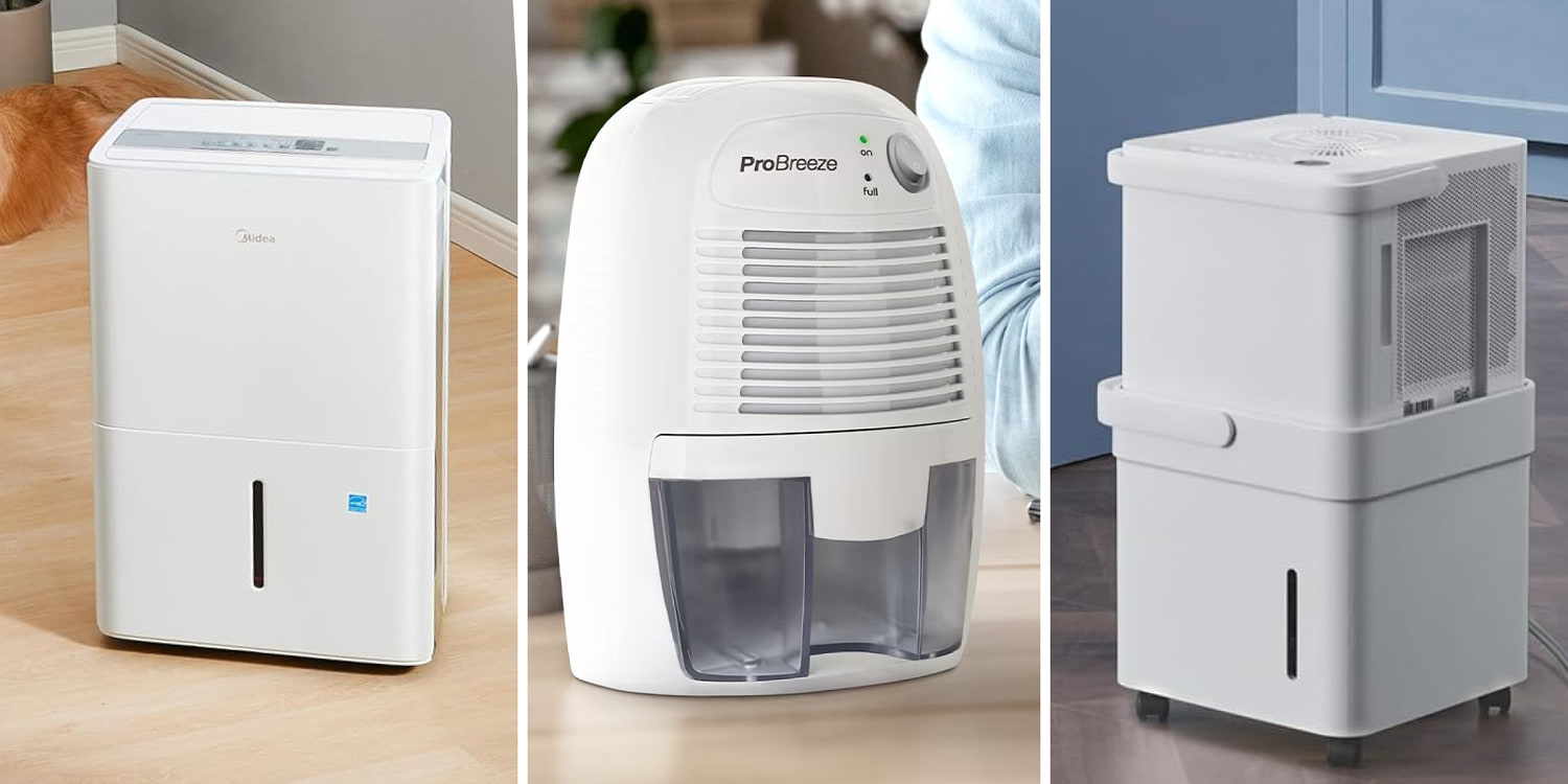
High-Volume Structural Extraction: Midea Cube Series
The Midea Cube represents a significant departure from traditional form factors by separating the mechanical compressor nest from the primary water reservoir. This nesting design addresses a major logistical flaw in residential dehumidifier deployment: bucket capacity limits.
+------------------------------------+
|        Midea Cube Mechanised Head  |
|  [Compressor] -> [Coil] -> [Fan]  |
+------------------------------------+
                  |  (Condensate Drop)
                  v
+------------------------------------+
|        Expanded 3x Reservoir       |
|        (Or Direct Gravity Drain)   |
+------------------------------------+
Traditional 50-pint units often feature small 12-to-15-pint buckets. When the bucket fills, a float switch cuts power to the compressor. If the user is away for 14 hours, the machine may only run for 4 hours before sitting idle, tanking the daily average extraction rate. By expanding the reservoir capacity by up to three times the industry standard without expanding the storage footprint during shipping, the Cube maintains longer continuous operational windows.
The machine utilizes an internal lift pump option, allowing it to route condensate vertically into a utility sink or out a window basin. This bypasses the reliance on gravity drains, which frequently fail due to airlocks or minor kinks in the vinyl discharge tubing.
Airflow Optimization and Static Pressure: Frigidaire Gallery Series
The Frigidaire Gallery models optimize a variable that manufacturers frequently obscure: Clean Air Delivery Rate (CADR) coupled with high static pressure fans. Removing moisture requires moving air across the coils efficiently. If a machine cannot cycle the entire volume of a room multiple times per hour, localized pockets of stagnant, high-humidity air will persist in corners and behind partitions.
Frigidaire's architecture utilizes a heavy-duty centrifugal fan that maintains high cubic feet per minute (CFM) ratings even as the intake filter becomes loaded with particulate matter. This model is optimal for spaces where air distribution is structurally choked, such as multi-room basements or crawlspaces with low overhead clearance.
The primary limitation of this design is acoustic output. The high-velocity fan generates a consistent decibel floor that makes it poorly suited for immediate living areas like bedrooms, where lower-velocity, multi-stage axial fans are preferable.
Low-Temperature Mitigation: LG PuriCare
The LG PuriCare addresses the low-temperature frost bottleneck through a dedicated electronic expansion valve (EEV) and an automated hot-gas bypass defrost system. Rather than simply turning off the compressor and waiting for ambient air to melt the frost, the system temporarily reroutes hot refrigerant gas directly from the compressor discharge back into the evaporator coil.
This hot-gas injection melts ice formations in minutes rather than hours, allowing the unit to return to active moisture extraction rapidly. For environments that fluctuate between 50°F and 60°F, this mechanical addition makes the PuriCare significantly more efficient than standard consumer units that rely on passive air-over-defrost cycles.
The True Cost of Ownership: An Analytical Framework
Purchasing a dehumidifier requires assessing the total cost of ownership (TCO) over a five-year operational horizon. The initial retail price tag is often a fraction of the total lifetime energy cost.
To calculate the efficiency of a machine, look past the pint rating and isolate the Integrated Energy Factor (IEF). The IEF measures the liters of water removed per kilowatt-hour ($\text{L/kWh}$) of electricity consumed.
$$\text{IEF} = \frac{\text{Liters of Water Extracted}}{\text{Total Electricity Consumed (kWh)}}$$
A machine with a low IEF will consume its retail value in electricity within 18 months of continuous seasonal operation.
| Metric | Compressor (Standard) | Compressor (Premium / EEV) | Desiccant |
|---|---|---|---|
| Optimal Temp Range | 65°F to 90°F | 50°F to 90°F | 33°F to 90°F |
| Average IEF Range | 1.30 – 1.60 $\text{L/kWh}$ | 1.80 – 2.10 $\text{L/kWh}$ | 0.60 – 0.90 $\text{L/kWh}$ |
| Primary Failure Node | Sensor Corrosion / Frost | EEV Mechanical Jam | Heating Element Burnout |
| Air Exhaust Temp | Ambient + 5°F | Ambient + 7°F | Ambient + 12°F |
The chart highlights a hidden variable: thermal rejection. Desiccant units reject significant sensible heat back into the space. If the goal is to dry out a hot, un-air-conditioned second-story room in July, a desiccant unit will raise the ambient temperature drastically, increasing the cooling load on the home's primary HVAC system. Conversely, in a cold basement during winter, this heat rejection acts as a helpful secondary thermal source.
Strategic System Deployment
To maximize system lifespan and guarantee moisture stabilization, execution must follow a rigid deployment protocol.
Elevation and Drainage
Never place a gravity-drain unit directly on a concrete floor if it is discharging into a floor drain several feet away. The lack of pitch prevents proper drainage, causing water to back up into the internal drip tray. This standing water creates a biological breeding ground for bio-films and mold spores, which are then aerosolized by the fan. Elevate the unit at least 12 inches off the ground on a solid platform to maximize the gravitational slope.
Placement and Air Stagnation
Placing a dehumidifier against a wall to save space restricts the intake plenum. Most consumer units require a minimum of 18 inches of clearance on all sides to prevent air recirculation. Recirculation occurs when the machine immediately draws its own freshly exhausted dry air back into the intake, triggering the humidistat to shut off prematurely while the rest of the room remains saturated.
Sensor Calibration Inversion
Built-in humidistats are notoriously inaccurate because they measure the relative humidity directly adjacent to the machine's damp coils. To achieve true atmospheric stabilization, bypass the internal sensor by setting the unit to continuous mode and wiring it to an external, wall-mounted digital humidistat placed on the opposite side of the room. This ensures the machine only runs when the entire room volume requires drying.
The final strategic move for any large-scale or problematic moisture zone is a strict rejection of single-node saturation. If a space exceeds 1,500 square feet or features complex partitioning, deploying two smaller units with high IEF ratings at opposite ends of the structure will consistently outperform a single, ultra-high-capacity unit positioned centrally. This distribution creates a balanced vapor pressure gradient across the entire architectural footprint, preventing localized structural rot while minimizing the peak electrical load on any single circuit.